Session Relay Node Architecture and Deployment
A Session Relay Node is designed to reduce potential heavy network traffic that may be apparent in deployments where remote sessions, between a user and a remote host, span geographies. In multi-region deployments and under certain circumstances, a user’s remote session in such deployments could exhibit a performance decrease that results in latency during their session.
This could be caused by how PAM communicates between its components via network connectivity. In a multi-node PAM deployment where remote sessions are being utilized, the network traffic routes from the user’s device through the PAM Master Node to the Session Manager (which may also be remotely located) and finally, to the destination host.
In most deployments, this traffic routing works well for a consistently quality remote session experience; however, when the user’s location is similarly located to the destination endpoint, whereas the Master Node is significantly remotely distant to both, routing to this remote Master Node can degrade this session experience.
It is this second scenario that the Session Relay Node looks to optimize by reducing the amount of heavy traffic that needs to occur between the user, destination endpoint and master node(s).
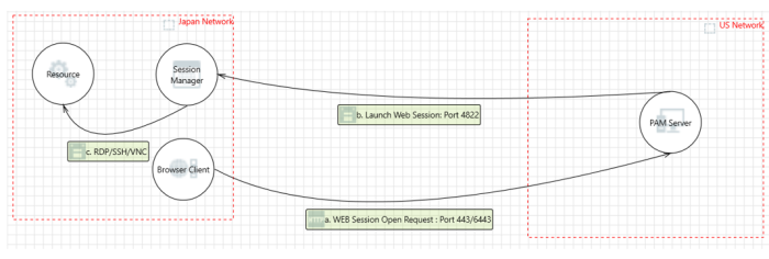
With an optimally deployed Session Relay Node, the heavier network communication like web session traffic is routed locally between the user’s device and the Session Relay Node, while only low volume traffic like authentication and permission information) is required to route through the Master Node.
This redirects high traffic communication and can improve a user’s session experience by keeping it more local to their and the destination endpoints geography.
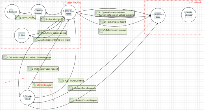
To further illustrate this deployment, let us take the example of a PAM deployment residing physically in the US East region and some users and destination endpoints located in Japan.
For a user sitting in Japan and accessing endpoints also located in Japan, heavy traffic routed through US East located Master Node may experience performance degradation.
With a Session Relay Node deployed in the same Japan location, this heavy session traffic now remains in Japan thus reducing the amount of “around the globe” communication necessary to establish and maintain this remote session.
If your PAM deployment, destination endpoints or user base spans across multiple geographies and the session experience involving these regions exhibits latency, then adding an appropriately located Session Relay Node to your deployment may help.
The remainder of this article will describe the Session Relay Node Considerations and Deployment procedures.
Considerations
When deliberating if a Session Relay Node may improve a session experience in your deployment, please consider the following:
-
Is your PAM deployment, including users, components, and destination endpoints, located in vastly remote geographies and remote session experience is noticeably and consistently “laggy” for users?
-
Have you already deployed a remote Session Manager component geographically closer to the destination endpoint?
-
Have you reviewed your network topography considering any blockers like VPNs, network scanners or analyzers, that may be introducing traffic degradation? If present, can these be removed, optimized or excluded from PAM traffic and communication?
-
Are the resources on the PAM server(s) running low? High CPU utilization, high memory usage or low disk space could be contributors to observed PAM performance reports. Increasing server resources and deploying additional PAM nodes like Session Managers or Master Nodes could alleviate high resource consumption.
-
Will your existing license key support the additional node requirement? A Session Relay Node consumes one additional node from your registered license key regardless of whether it is deployed to an existing node or as a new node.
-
The Federated Sign-in Module (FSM) is a required PAM component on all Master and Session Relay Nodes. Instructions to install or update the federated sign in module can be found https://help.xtontech.com/content/installation/federated-sign-in-module/federated-sign-in.htm
Configuration
Relay Node can be installed to a new PAM node, or an existing Remote Node can be configured to also support the Relay Node function.
Either deployment will consume one Node from the registered license key.
New Relay Node Deployment
This section will include the procedure required to install a PAM Session Relay Node to a new server.
This server's location should be carefully chosen to maximize the benefits of the Relay Node.
The server can be either virtual or physical and should have at least 2 CPUs, 8 GB of memory available and 100 GB of disk space for the PAM services to consume. Valid SSL certificates will also be required to secure traffic between the various components.
PAM Web Configuration
-
Login to PAM web console with a System Administrator account.
-
Create a new local user that will be used exclusively for the authenticating between the Master and Relay Nodes. If you are deploying multiple Relay Nodes, you may use the same local user for each relay node or choose to create a unique local user for each relay node, either is supported.
-
Grant this local user account the Global Role Service
-
Create an API token for this Relay Node local user account.
-
On the Administration > Settings > Parameters page, locate the parameter Support Relayed Sessions, set it to Enabled and click the Save button.
Relay Node Configuration
-
On the server, run the PAM installer and select the following options:
-
Internal Database.
-
Directory Service.
-
Application GUI.
-
Job Engine (only select this option if the node will also support remote Job Engine executions).
-
Session Manager.
-
Federated Sign-In.
-
-
Active Directory integration is not required nor recommended. Leave empty and continue.
-
When the installation is complete, safe the deployment’s configuration and passwords to a safe and secure location.
-
Open a browser and login to the PAM web console using the default System Administrator account created during installation. Click the Initialize button to initialize the database and wait until this operation completes. After it finishes, you may log out of PAM and close your browser.
-
Generate a self-signed or obtain valid SSL certificates whose CN field matches the master and relay nodes host names.
-
Open the file $PAM_HOME/web/conf/catalina.properties in a text editor and locate the parameter named cas.tgc.crypto.signing.key. Copy this signing.key value from your Master Node and paste it to this parameter on the relay node.
-
Open the file $PAM_HOME/web/conf/catalina.properties in a text editor and add the following new parameters whose values match your Master Node deployment. If you have multiple Master Nodes, you will need to add parameters for each master node using an indexed configuration [0], [1], [2], etc.
Example placeholders in these parameters, noted by the value surrounded by {}, should be replaced with the values specific to your deployment.
Copyxtam.remote.enabled=false
xtam.remote.url={https://pam:6443/xtam}
xtam.remote.user=relay
xtam.remote.id={masterNodeServerName}
xtam.remote.token={RelayNodeAccountToken}In the case of multiple Master Nodes, indexed configuration may look like this:
Copyxtam.remote.enabled[1]=false
xtam.remote.url[1]={https://pam:6443/xtam}
xtam.remote.user[1]=relay
xtam.remote.id[1]={masterNodeServerName}
xtam.remote.token[1]={RelayNodeAccountToken} -
In the same file, add these new parameters based on your deployment requirements:
-
Copy
xtam.relay.node=enabled -
Copy
xtam.relay.name={RelayNodeName}-
Choose a short and descriptive name of this Relay Node that will be used to identify it in the Application Node list and the Connect menu that the user will select.
We recommend choosing a name that represents the Relay Node’s location like US East Relay or Japan Relay.
-
-
-
If the Relay Node is also being used for Job Engine execution, then also add this new line:
Copyxtam.remote.enabled=true -
In order for relay node to broker sessions with session managers based on proximity group configuration, add/update the below property:
Copyxtam.relay.session.manager.lookup=enabled/disabled (default=enabled) -
Next, SSL certificates will be imported to secure the component communications.
-
Import the SSL certificate from the Master Node(s) using the SSLImport command.
Example shown below:
-
Windows: from $PAM_HOME, execute bin\PamDirectory.cmd SSLImport pam.company.com 443
-
Linux: from $PAM_HOME, execute bin/PamDirectory.sh SSLImport pam.company.com 443
-
-
Import the SSL certificate from the Relay Node itself.
Example shown below:
-
Windows: from $PAM_HOME, execute bin\PamDirectory.cmd SSLImport pam.company.com 443
-
Linux: from $PAM_HOME, execute bin/PamDirectory.sh SSLImport pam.company.com 443
-
-
Import the SSL certificate from each Session Manager configured with the Master Nodes.
Example shown below:
-
Windows: from $PAM_HOME, execute bin\PamDirectory.cmd SSLImport pam.company.com 443
-
Linux: from $PAM_HOME, execute bin/PamDirectory.sh SSLImport pam.company.com 443
You may disable Session Manager resolution from the Master Node by adding xtam.relay.session.manager.lookup=disabled to the catalina.properties configuration file on the Master Nodes.
-
-
-
Restart the PamManagement (Windows) or pammanager (Linux) service on the Relay Node to complete the configuration.
Testing
After the deployment is complete, it is now time to test the functionality of the Session Relay Node.
This testing will be performed by a System Administrator.
First, let us confirm that the Relay Node is online and communicating with your PAM Master Node(s).
-
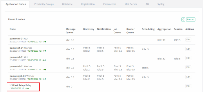
Navigate to Administration > Settings > Application Nodes and locate the presence of your Relay Node. It will be shown with the name that was added to the configuration in our previous sections followed by the label Relay. For example, US East Relay:Relay
-
If the node is online, it will be shown in green font accompanied with an up arrow; conversely if the node is offline, it will be shown in red font accompanied with a down arrow. The node must be online before testing continues.
Next, it is time to check session connectivity.
-
Navigate to an existing record or create a test record.
-
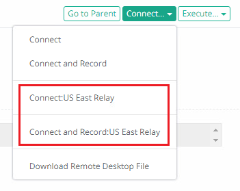
From the Record View page, open the Connect dropdown menu and select the Connect option that is shown with the Relay Node name appended to the end.
-
After the Relay Node Connect option is selected, a new Relay Node Redirection browser window or tab will open. An automatic redirect attempt to the Relay Node page will begin and if successful, the user’s remote session will then connect to the destination endpoint from the indicated Relay Node. If the automatic redirect attempt fails after five seconds, a Redirect button will appear that the user must click to continue.

-
Test the remote session functionality to confirm the session connected to the destination endpoint successfully and then complete the session.
Finally, we will confirm that this remote test session was routed through the Relay Node.
-
From the record’s Session report or the Report Center’s Session report, locate the previous test session that is now complete.
-
In the Session Manager column of this session, the Relay Node server’s name will be displayed, confirming that the Relay Node connected this session.

SSH Proxy with Relay Node
Requirements
Ensure Relay node setup is complete following instructions from the above article.
Relay Node Configuration
-
Open the file $PAM_HOME/web/conf/catalina.properties in a text editor and add the following new parameters:
Copyxtam.ssh.proxy=enabled
xtam.ssh.proxy.port=2022 -
Restart Pammanager (Linux) or pammanagement service on Windows.
Testing SSH Proxy connection with Relay node
-
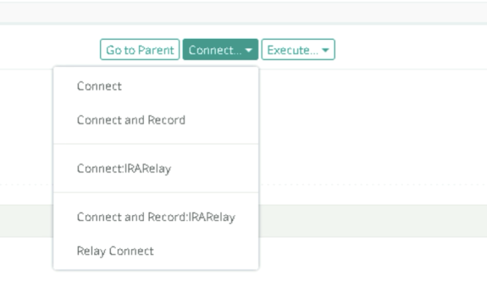
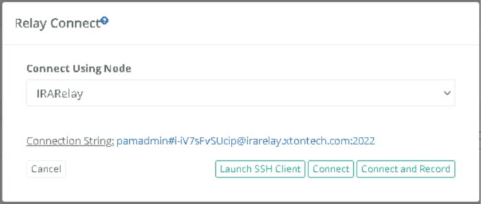
In case of Relay node, users can get the connection string by navigating to the record to be connected and clicking on Connect > Relay Connect and clicking the connection string value to the clipboard:
The instructions to connect and test using native tools such as Putty are available here.
Replace the Hostname with the hostname from the connection string captured in #1.
RDP Proxy with Relay Node
Requirements
-
Ensure Relay node setup is complete (PAM Web Configuration).
Relay Node Configuration
-
Open the file $PAM_HOME/web/conf/catalina.properties on the relay node in a text editor and add the following new parameters:
Copyxtam.rdp.proxy=enabled
xtam.rdp.proxy.port=3388 -
Restart Pammanager (Linux) or pammanagement service on Windows.
Testing RDP Proxy connection with Relay node
-
Follow steps as given in https://help.xtontech.com/content/administrators-and-power-users/secure-remote-sessions-connect/rdp-client-proxy-sessions.htm.
-
In the Relay Connect popup, select the correct Relay node and press Download Remote Desktop File:
-
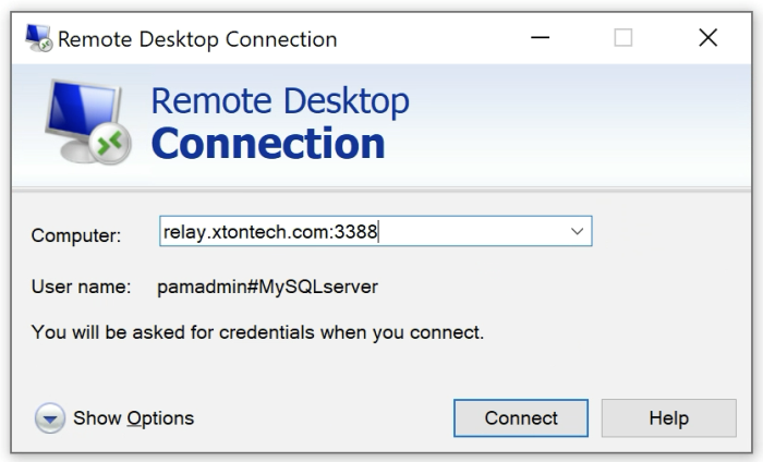
The instructions to connect and test using native tools such as Windows RDP Client are available here: https://help.xtontech.com/content/administrators-and-power-users/secure-remote-sessions-connect/rdp-client-proxy-sessions.htm.
-
Replace the Hostname with the hostname from the connection string captured in #1.

Command Line Secure Shell Interface (SSH) with Relay Node
Requirements
-
Ensure Relay node setup is complete (PAM Web Configuration).
-
Ensure SSH proxy on relay node is complete (SSH Proxy with Relay Node Configuration).
Testing SSH connection with relay node
-
The instructions to connect and test using native tools such as Putty.
-
Replace the Hostname with the hostname of the relay node.
Limit Relay Node option to specific containers or records
In some cases, it may be required to associate relay nodes to specific containers (folders or vaults) or records.
Requirements
-
Ensure Relay node setup is complete (PAM Web Configuration).
Additional Configuration
-
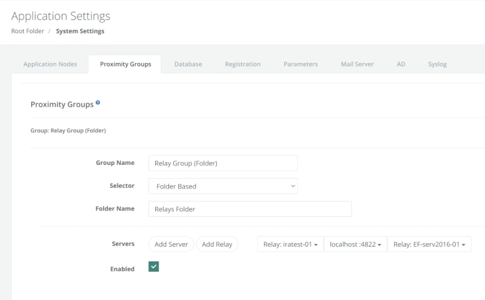
Set the Settings > Use Proximity Groups to Resolve Relays property to Enabled.
-
From Settings > Proximity Groups, Select the Add Relay button and choose the Relay node to be associated.
